If you haven’t read the previous posts on this project, the tldr is that I’m building a chess robot named Mags that moves pieces around using an electromagnet underneath the board.
My friends and I finally finished the first CAD iteration of Mags.
If you want to take a closer look, check out our CAD. Here’s the Onshape link.
Design Objectives #
I’ll begin with our overarching objectives.
I want to build something better than what already exists. Some issues with existing robotic chess boards are:
- Piece detection: Magnetic piece detection is invisible and more reliable than touch sensors used by some boards
- Compactness: Robotic chessboards I’ve seen are at least 80mm thick. Mags should be thin.
- Aesthetics: Most robotic chessboards look like a normal chess set. But I want Mags should look more modern.
- Speed: I like things that move fast. Mags should be quick.
- Personality: Playing chess against a robot should be fun. Mags could offer takebacks and advice in easy mode, and roast you in hustler mode.
Next I’ll talk about the design choices that address these issues.
Exterior #
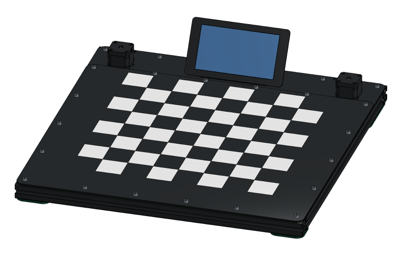
- Flipped motors: Reduces thickness to 40 mm and gives us space for bigger motors.
- Touchscreen: Gives Mags personality. You can request takebacks and Mags can tell you how bad your moves are.
- Carbon fiber board: Way cooler (and stiffer) than wood veneer. The squares will be on a vinyl sheet, which helps keep the playing surface flat.
- 3030 Extrusion frame: Easy to iterate quickly with. By tapping the ends, we can (relatively) easily make a stiff and square frame. 2020 extrusion is too small. We tried.
Gantry #
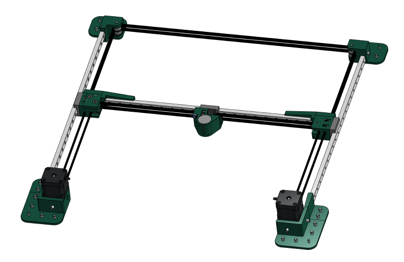
Here are the notable design choices:
- MGN12C Linear Rails: Compact, stiff, and smooth. 27mm tall is the perfect height for 3030 extrusion. Expensive but worth it.
- CoreXY: Moving parts are lightweight. Two tensioners on the carriage can straighten the X-axis.
- 3D printed parts: Fast iteration. Enables compact and complicated parts.
- Raspi Pico: Controls motors using Klipper (which doesn’t work on Teensies). Klipper is awesome.
Closeups #
In this section I’ll write about the more subtle design choices.
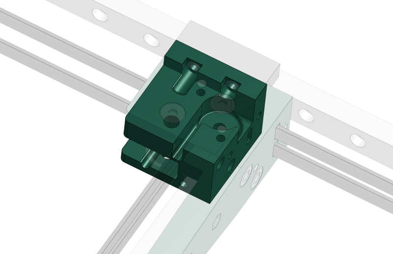
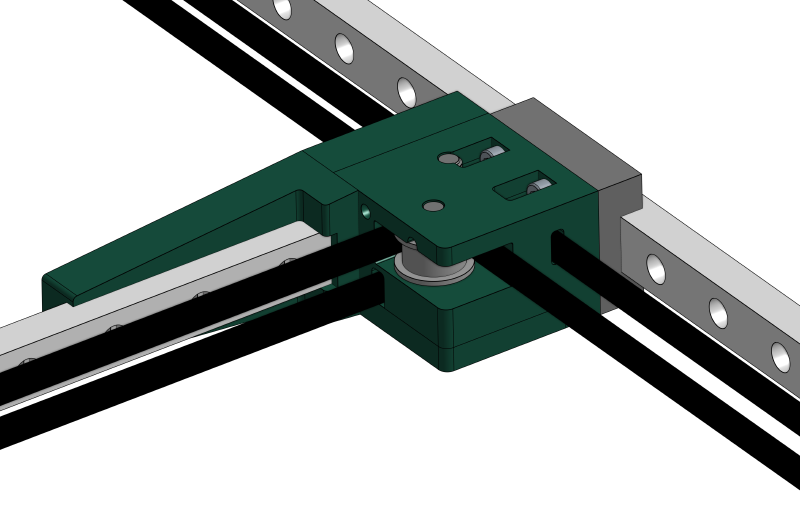
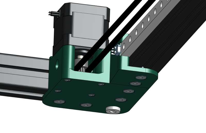
Pulley Block #
The rail mount is a separate part so that we can print it flat on the bed for strength and dimensional accuracy. The lid allows us to assemble the top pulley without cantilevering it. The parts are precisely located to eachother with press-fit dowel pins. This is important because we want the rails to be as perpendicular as possible.
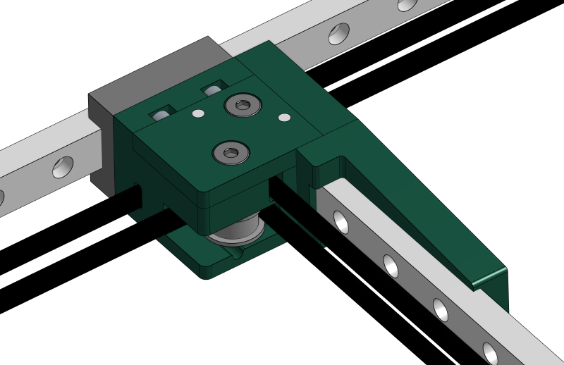
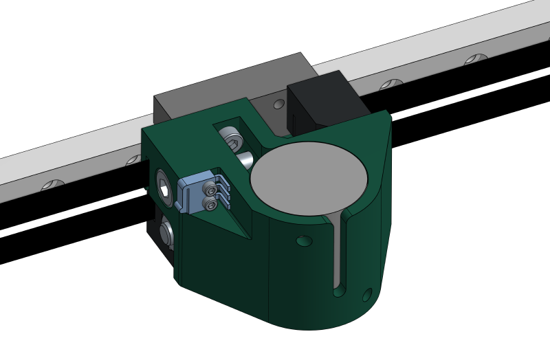
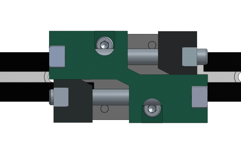
Carriage #
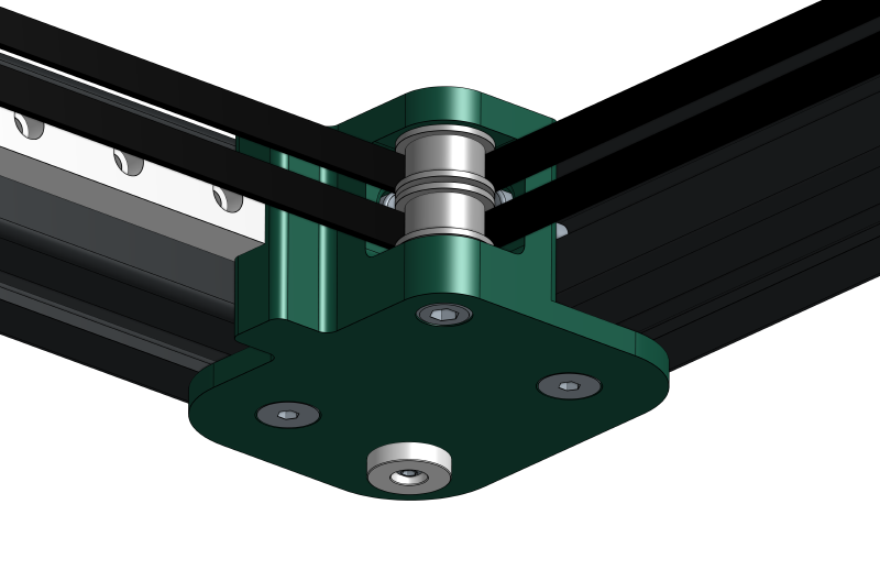
Corner Mount #
Motor Mount #
Board #
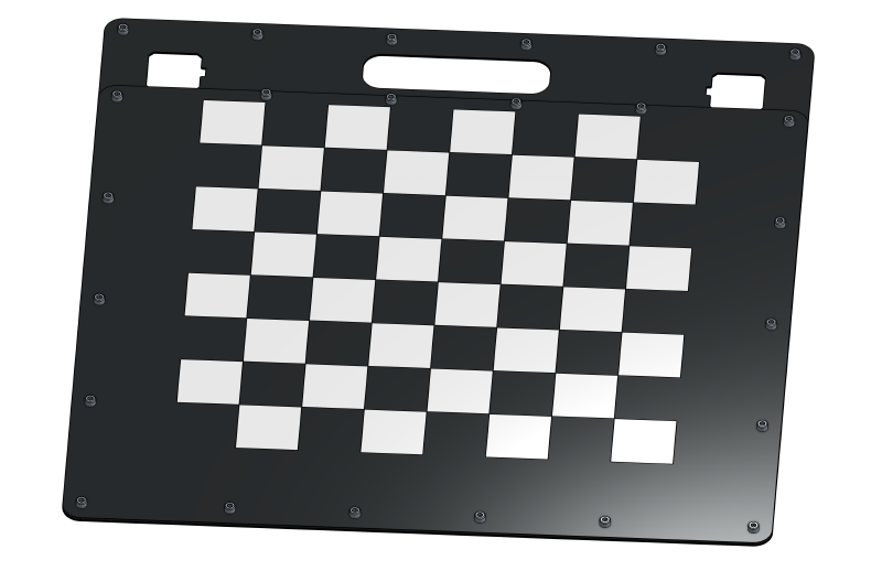
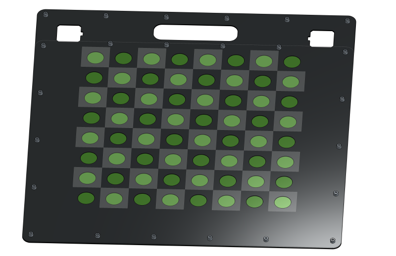
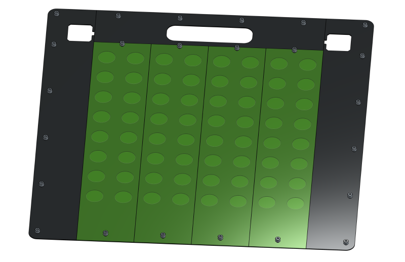
On the bottom layer, we have more delrin spacers and four 0.8x100x400mm PCBs. These PCBs detect which squares have pieces on them. Each PCB contains sixteen hall-effect sensors and a multiplexor breakout board.
Summary #
We’ve now designed a cool chess robot, but actually building it will be hard. I’ll order parts by the beginning of IAP (MIT’s january term) so that we can hit the ground running with manufacturing and assembly.